Why Choose TNC Cable Assemblies for RF Applications?
TNC cable assemblies remain a practical choice when RF systems need a secure connection under vibration, repeated handling, or changing weather. Their threaded coupling helps resist accidental loosening, while the interface supports consistent signal transfer across connected equipment. The details matter: cable type, impedance, frequency range, shielding, and termination quality all affect performance. A connector alone cannot fix a poorly assembled cable.
The demand for dependable wireless infrastructure continues to grow. The Ericsson Mobility Report (June 2024) tracks expanding 5G networks and rising traffic, while the ITU’s Facts and Figures 2023 estimated that 5.4 billion people were online. These reports describe the broader connectivity landscape, not TNC connector demand specifically. Dr. David M. Pozar’s Microwave Engineering explains the importance of transmission-line behavior and impedance matching; applied here, that means choosing an assembly whose electrical characteristics suit the full RF path. I can’t verify a verbatim, TNC-specific quotation from Pozar, so I won’t invent one.
A Tnc Cable Assembly can be useful in test equipment, antennas, and radio systems where a secure threaded connection is valued. Check the manufacturer’s frequency rating and return-loss data, then inspect the crimp or solder termination and cable routing. Small flaws show up fast. Even a premium connector may underperform when the cable is sharply bent or poorly installed. That is the part teams sometimes overlook.
What Is a TNC Cable Assembly?
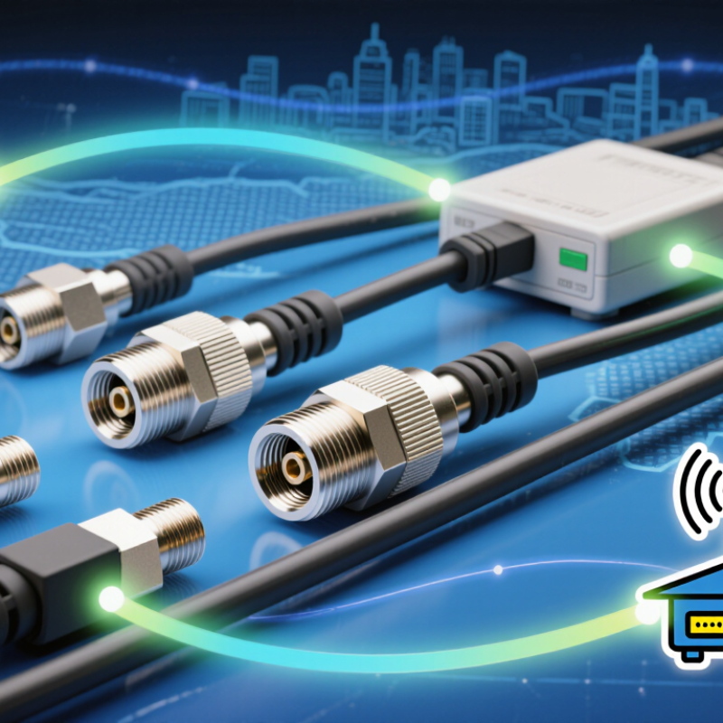
A TNC cable assembly is a coaxial cable fitted with TNC connectors on one or both ends. Each connector joins the cable’s center conductor and shield to a matching RF interface. The threaded coupling holds the connection firmly, even when vibration might loosen a push-on connector. Inside, the center conductor carries the signal, while the dielectric and outer shield help maintain impedance and limit interference. Many RF systems use 50-ohm TNC assemblies, but the impedance must match the equipment.
The assembly’s performance depends on more than its connector type. Cable length, operating frequency, attenuation, and bend radius all matter. A technician should check the datasheet for frequency range and loss, then inspect the connector and cable jacket before installation. At a test bench, a loose coupling or sharply bent cable can affect measurements. The label alone tells you surprisingly little. In practice, TNC can be a useful choice for equipment exposed to movement, but it is not automatically the best fit for every RF setup. Matching the cable, connectors, and system requirements takes care—and sometimes a second check.
How TNC Connectors Support Reliable RF Connections
Why Choose TNC Cable Assemblies for RF Applications?
How TNC Connectors Support Reliable RF Connections
TNC connectors use a threaded coupling that helps keep the connection secure when equipment vibrates or cables are moved. That stability matters in RF systems, where a loose interface can cause signal loss or intermittent performance. A properly matched 50-ohm cable assembly also helps maintain consistent impedance from one end of the link to the other. Small details count.
The threaded design can provide a more dependable hold than a push-on connection, especially in field equipment or test setups. Still, TNC connectors are not automatically weatherproof; sealing depends on the connector design and how it is installed. Check the operating frequency, cable type, and interface condition before choosing an assembly. A worn center contact or damaged thread may undermine an otherwise sound connection. It is easy to overlook.
Tips: Hand-start the threads to avoid cross-threading, then tighten according to the connector maker’s guidance. Keep the mating surfaces clean and inspect them for dents or debris. Avoid twisting the cable while tightening. A quick inspection can prevent trouble later.
Why Choose TNC Cable Assemblies for RF Applications? — How TNC Connectors Support Reliable RF Connections | RF Connection Consideration | How TNC Cable Assemblies Help | Practical Selection Notes |
| Threaded coupling | The threaded coupling mechanism helps keep the connector halves securely engaged and reduces the chance of accidental loosening from movement or vibration. | Confirm that the mating connector has the matching TNC interface and is properly tightened according to the connector manufacturer’s instructions. |
| Impedance matching | TNC connectors are available in 50-ohm and 75-ohm versions, supporting RF systems designed around either impedance. | Match the connector, cable, and equipment impedance throughout the signal path. Mixing 50-ohm and 75-ohm components can cause reflections and measurement errors. |
| Frequency capability | TNC interfaces are used in RF applications across a broad frequency range, with some designs specified for operation up to approximately 11 GHz. | The usable frequency depends on the specific connector, cable, assembly construction, and installation. Check the assembly’s rated frequency and electrical test data. |
| Connection repeatability | The defined threaded interface provides a consistent mechanical connection when compatible components are assembled correctly. | For repeatable test or production setups, use the specified tightening method and inspect connectors for worn threads, contamination, or damaged contacts. |
| Cable and assembly performance | A cable assembly combines the TNC connectors with a selected coaxial cable to carry RF signals between equipment and antennas or other system components. | Evaluate insertion loss, shielding, return loss or VSWR, cable flexibility, and assembly length for the intended frequency and installation conditions. |
| Environmental exposure | The threaded connection can provide a secure mechanical joint, while suitable sealing and materials can support use in demanding environments. | A threaded interface alone does not make an assembly waterproof. Verify the specified ingress protection, temperature range, corrosion resistance, and environmental rating. |
| Typical applications | TNC cable assemblies are used in RF test equipment, antennas, wireless infrastructure, navigation systems, and other coaxial signal connections. | Choose an assembly with the correct connector gender, impedance, cable type, length, and environmental rating for the equipment and installation. |
Key Electrical and Mechanical Characteristics
TNC cable assemblies combine a 50-ohm interface with a threaded coupling, helping maintain stable contact when equipment faces vibration or repeated handling. Published industry specifications commonly place standard TNC connectors in the DC–11 GHz range. Treat that figure as a practical reference, not a guarantee: the cable, connector pair, and assembly quality all affect usable bandwidth. IEC 61169-17:2013 specifies TNC connector interface requirements and test methods, but it does not make every assembly perform identically.
Electrically, check impedance, return loss, and insertion loss across the intended frequency band. A mismatch can reflect energy back toward the source. That matters in a crowded test rack. Mechanical details matter too: threaded coupling resists accidental loosening, while proper cable strain relief reduces stress at the connector junction. MIL-STD-348B provides standardized connector interface dimensions, useful when checking mating compatibility across equipment.
Real assemblies still have limits. A tight connector cannot compensate for a kinked cable, poor termination, or excessive bend near the backshell. Inspect the interface, follow the specified torque, and verify performance with suitable test equipment. One detail is easy to overlook: repeated mating can wear contacts, even when the exterior looks sound. For critical links, record test results after installation rather than relying on nominal specifications alone.
Common RF Applications for TNC Cable Assemblies
TNC cable assemblies are common in RF systems that need a secure, threaded connection. Their coupling can help resist loosening when equipment experiences vibration, such as on vehicle-mounted antennas or outdoor communication enclosures. The connector alone does not guarantee weather resistance; the full assembly needs suitable sealing and environmental ratings.
A typical use is connecting an antenna to a radio, receiver, or base station. TNC assemblies also appear in wireless infrastructure, navigation equipment, and field measurement setups. On a test bench, a technician might connect a signal generator to an antenna or analyzer, where stable contact helps produce repeatable readings. Small details matter: check impedance, operating frequency, cable loss, and connector gender before installation. A mismatch can reduce signal quality.
They are useful, but not automatically the right choice. A threaded connector is not a cure for poor cable routing. Tight bends, an unsupported cable, or moisture at the interface can still cause trouble. In practice, matching the assembly to the equipment’s frequency range and installation environment matters more than choosing a connector by appearance. Even experienced installers can overlook cable strain.
How to Choose a TNC Cable Assembly for Your System
Choose a TNC cable assembly by matching its impedance, frequency range, and length to your system. Most RF setups use 50-ohm components; a mismatch can increase reflections and weaken the signal. Many conventional TNC assemblies are rated up to 11 GHz, but the complete assembly’s rating depends on its connector, cable, and termination. IEC 61169-17:2013 and MIL-STD-348B provide TNC interface requirements and dimensions. They do not guarantee the performance of a finished cable assembly.
Check insertion loss and return loss across your operating band, not just at one frequency. Then consider cable length, bend radius, temperature, and vibration. A cable routed around a metal chassis may need a tighter bend than your lab setup allows. Confirm the mating interface and measure a sample assembly under realistic installation conditions. I still treat a catalog rating as a starting point, not proof of system performance.
Tips: Ask for test data across your full frequency range. Verify the cable’s bend radius before routing. Keep the assembly as short as practical, but not taut.