background

Blog

How to Choose a Solar Panel Mounting Structure?

Choosing a solar panel mounting structure is not a minor purchasing decision. It determines how panels resist wind, snow, corrosion, and daily thermal movement. It also affects installation speed, maintenance access, drainage, and long-term energy yield.

The global solar market is expanding rapidly. The IEA Photovoltaic Power Systems Programme reported more than 400 gigawatts of new photovoltaic capacity installed worldwide in 2023. IRENA’s Renewable Capacity Statistics 2024 recorded global solar capacity exceeding 1.4 terawatts by the end of that year. Behind every module is a physical support system. That system must perform reliably for decades, not merely look affordable on a quotation.

A suitable solar panel mounting structure begins with site evidence. Roof material, slope, wind exposure, snow load, soil condition, and local corrosion risks all matter. A coastal project may need stronger aluminum alloys or protected fasteners. A ground-mounted array may require deeper foundations after a geotechnical review. The wrong choice can create water leaks, cable strain, or uneven loading across modules.

Industry standards such as ASCE 7, Eurocode provisions, and UL 2703 can guide structural and electrical safety decisions, depending on the project location. However, standards do not replace engineering judgment. Product brochures often simplify real conditions. They may not show installation errors, difficult access, or changing weather patterns. This guide compares roof, ground, carport, fixed-tilt, and tracking systems, while recognizing an uncomfortable truth: the cheapest structure is rarely the lowest-cost structure over its full service life.
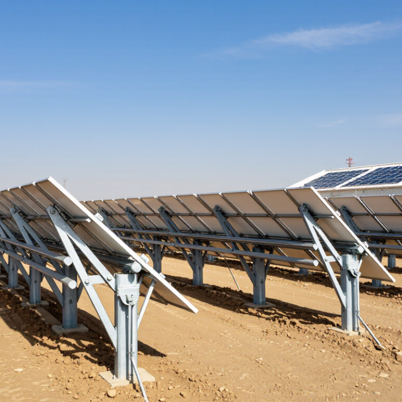
How to Choose a Solar Panel Mounting Structure?

Solar Panel Mounting Structures: Purpose, Components, and Main Types

Solar panel mounting structures carry modules safely while preserving roof integrity and electrical performance. Their purpose extends beyond holding panels. They resist wind uplift, snow loads, corrosion, thermal movement, and maintenance stress. IRENA’s Renewable Capacity Statistics 2024 recorded 1,419 GW of global solar capacity by the end of 2023. That scale makes structural reliability increasingly important.

A typical system includes rails, clamps, brackets, fasteners, bonding components, posts, and foundations. Rooftop systems commonly use penetrating anchors, ballast, or specialized brackets. Ground-mounted arrays rely on driven piles, concrete foundations, or screw foundations.

Fixed-tilt structures are simpler and usually require less maintenance. Tracking structures can increase energy capture, but they add motors, controls, and failure points. The compromise is real.

Choosing a structure starts with the site. Check roof material, rafter spacing, drainage paths, wind exposure, snow conditions, soil resistance, and coastal corrosion risk. IEC 62548 addresses photovoltaic array design and installation practices, while local structural codes define loading requirements. IEA PVPS Trends 2024 reported more than 400 GW of solar additions during 2023, showing how quickly deployment is expanding.

Yet rapid growth can encourage rushed decisions. A neat drawing can still hide weak anchors or poor cable routing. Inspect fasteners, seals, grounding paths, and foundation alignment before approval. Sometimes, the cheapest frame is simply the most expensive repair waiting to happen.

Assessing Site Conditions and Solar Installation Requirements

Choosing a solar panel mounting structure begins with the site, not the panel. Inspect the roof, ground, or carport before comparing frame designs. Measure roof pitch, available area, and structural strength. Check for cracks, water damage, loose fasteners, or aging materials. A small weakness may become serious under wind and snow loads.

Sun exposure also shapes the installation requirements. Record shade from trees, chimneys, nearby buildings, and seasonal changes. Even short morning shadows can reduce annual production. For ground systems, examine soil density, drainage, frost depth, and slope. Rocky or unstable soil may require different foundations. The mounting height should leave space for vegetation control and safe maintenance.

Local wind, snow, seismic, electrical, and fire rules must guide the final design. Ask a qualified structural professional to verify load calculations and attachment details. Use corrosion-resistant materials where salt, humidity, or agricultural chemicals are present. Plan cable routes carefully, keeping them away from standing water and sharp edges. Leave enough access for inspection and cleaning.

Small details matter. A rushed survey can cause expensive changes later. It is tempting to choose the cheapest structure, but weak assumptions can undermine reliability. I would recheck measurements after installation, because drawings do not always match real roof conditions. A practical mounting system should fit the site, support safe work, and remain serviceable for many years.

How to Choose a Solar Panel Mounting Structure? - Assessing Site Conditions and Solar Installation Requirements

Basic wind pressure reference: As site wind speed increases, the pressure acting on solar panels and mounting structures rises rapidly. The values below are calculated using q = 0.613V², where q is pressure in N/m² and V is wind speed in m/s at standard sea-level air density.

Use local building codes, roof height, terrain exposure, panel tilt, snow load, roof condition, and structural capacity before selecting a fixed, ballasted, or ground-mounted structure. These calculated values are for preliminary assessment and are not a substitute for project-specific structural engineering.

Choosing Between Roof, Ground, Pole, and Tracking Mounts

How to Choose a Solar Panel Mounting Structure?

Choosing Between Roof, Ground, Pole, and Tracking Mounts

The mounting structure affects energy yield, maintenance, and installation risk. Roof mounts use existing space and usually need less steel. They suit buildings with strong, newer roofs and limited land. However, roof repairs become harder after installation. A shaded roof can also reduce output across an entire array.

Ground mounts offer easier access, better ventilation, and flexible panel orientation. They need clear land, drainage planning, and stronger foundations. The IEA PVPS Trends 2024 report states that global photovoltaic capacity exceeded 1.6 terawatts by the end of 2023. That scale increases pressure on suitable land. Pole mounts work well for small systems, especially where snow, uneven ground, or security concerns matter. They can cost more per panel, though. Tracking mounts follow the sun and may increase energy production by roughly 15–25% compared with fixed systems, depending on location. NREL’s 2024 Annual Technology Baseline shows that tracking is widely considered in utility-scale designs, but added motors and controls increase maintenance exposure.

Tips: Check roof age, wind loads, soil strength, shading, and service access before comparing prices. Ask for a stamped structural review. A cheap mount is not always economical. I have seen designs focus on peak output while ignoring muddy access roads and replacement work. That is a costly oversight. Reassess the choice using local weather data, not assumptions.

Comparing Materials, Durability, Load Capacity, and Adjustability

How to Choose a Solar Panel Mounting Structure?

Material selection affects corrosion resistance, weight, cost, and installation effort. Aluminum rails are light and easy to handle on rooftops. However, they may need stronger profiles in areas with heavy wind or snow. Galvanized steel offers greater stiffness and often supports larger spans. Its protective coating can weaken after cutting or drilling. Stainless steel resists corrosion well, especially near saltwater. It usually costs more and adds weight. I have found that mixed-metal systems require careful isolation to prevent galvanic corrosion.

Durability depends on more than the frame material. Check the fasteners, clamps, coatings, drainage paths, and connection points. Water trapped around a bolt can cause hidden rust. A structure should also match the roof’s expected service life. Review wind uplift, snow load, seismic movement, and panel weight using local engineering requirements. Do not rely on appearance alone. A thick-looking rail can still fail at a poorly designed joint.

Load capacity must include panels, cables, maintenance loads, and environmental forces. Adjustable structures can improve energy production by changing tilt or orientation. Yet more moving parts create extra inspection needs. Hinges may loosen. Bolts may need retightening. Fixed systems are simpler, but they may perform less efficiently on complex roofs. During site planning, measure roof angles, shading, and access space. A small adjustment range may be enough. Sometimes, I have overestimated the value of adjustability when a simpler structure would have reduced installation risks.

Verifying Installation Methods, Safety Standards, and Maintenance Needs

Choosing a solar mounting structure starts with verifying the installation method, not browsing attractive profiles. A roof system needs measured rafter spacing, roof condition, drainage paths, and local wind and snow data. Ground systems require geotechnical checks, pile depth, corrosion exposure, and equipment access. ASCE 7-22 provides the wind and snow load framework, while IEC 62548 addresses photovoltaic array design and installation practices. Ask for stamped calculations, fastening details, and a clear load path from module to foundation.

Safety details deserve close inspection. Components should have documented structural testing, electrical bonding, and corrosion resistance. UL 2703 covers mounting-system bonding and grounding requirements in applicable markets. The U.S. Department of Energy’s Operations and Maintenance Best Practices report recommends documented inspections, torque checks, vegetation control, and thermal imaging where appropriate. Small omissions matter. A loose clamp can become a damaged module after repeated thermal movement.

Maintenance needs should influence the structure before purchase. Leave safe walking clearance around inverters, drainage points, and inspection zones. The IEA PVPS Task 13 research commonly reports photovoltaic degradation near 0.5% annually, but poor cleaning access or hidden corrosion can accelerate losses. A design may look efficient on paper. In practice, removing one panel for repair can expose an awkward mistake. Review fastener materials, replacement access, inspection frequency, and written maintenance records with the installer.

How to Choose a Solar Panel Mounting Structure? - Verifying Installation Methods, Safety Standards, and Maintenance Needs

Mounting Structure Typical Application Installation Method to Verify Key Structural and Safety Checks Wind and Snow Considerations Maintenance Requirements Common Advantages Main Limitations
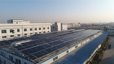
Roof-Mounted Rail System Sloped residential or commercial roofs with suitable structural framing. Locate rafters or structural members before drilling. Confirm flashing, waterproofing, attachment spacing, rail alignment, module clearances, and cable routing. Verify roof condition, rafter capacity, fastener compatibility, corrosion resistance, bonding/grounding, and compliance with the applicable electrical and building codes. Use site-specific wind uplift and snow-load calculations. Edge and corner zones usually require closer attention because wind pressures can be higher. Inspect roof penetrations, flashing, fasteners, clamps, bonding paths, corrosion, and cable support at least annually and after severe weather. Efficient use of existing roof area; generally low visual impact and relatively low material usage. Requires roof penetrations and a roof in good condition; repairs may require temporary panel removal.
Ballasted Flat-Roof System Flat or low-slope roofs where penetrations are restricted or undesirable. Confirm roof membrane compatibility, ballast layout, equipment access, drainage paths, separation layers, and the calculated friction or restraint system. Verify roof dead-load capacity, concentrated-load limits, uplift resistance, fire classification, wind-tunnel or engineering assumptions, and safe maintenance walkways. Ballast quantity and layout depend on wind exposure, building height, parapets, roof zones, module tilt, and local snow conditions. Do not use generic ballast values. Check ballast displacement, membrane condition, drainage, biological growth, module clamps, cable management, and debris accumulation. No or few roof penetrations; installation can be suitable for some membrane roofs. Adds permanent roof load; wind and drainage design are critical, and access paths consume roof area.
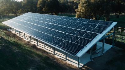
Fixed-Tilt Ground-Mount System Open land, brownfield sites, agricultural areas where foundations and site access are available. Complete a geotechnical review, set out pile or footing locations, verify foundation depth or concrete design, control row spacing, and install modules at the engineered tilt and orientation. Check soil bearing capacity, pile pull-out and lateral resistance, foundation settlement, corrosion category, grounding, fencing, drainage, and clearance from public access. Design for local basic wind speed, terrain, topography, snow load, frost depth, seismic effects, and terrain exposure. Array edges and end rows often govern design. Inspect foundations, posts, torque or fasteners, module clamps, grounding, vegetation clearance, erosion, drainage, and corrosion. Good accessibility, straightforward inspection, and flexible orientation; often easier to expand than a roof array. Needs land, civil works, permitting, vegetation control, and protection against unauthorized access or animals.
Pole-Mounted System Small to medium arrays where limited ground area or increased module elevation is useful. Verify pole diameter, embedment depth, concrete foundation, bracing, equipment clearances, tilt adjustment, and safe access for service work. Check overturning, bending, fatigue, soil conditions, corrosion at the ground line, grounding electrode arrangements, and structural access requirements. Elevated panels can experience significant wind moments. Design must account for gusts, exposure, array area, pole height, snow accumulation, and local soil resistance. Inspect pole-to-foundation connection, corrosion near grade, bolts, braces, module clamps, cable protection, and vegetation or animal damage. Uses relatively little land and can improve clearance from snow, vegetation, or minor flooding. Higher structural loads and foundations may increase cost; elevated equipment can be more exposed to wind and lightning.
Single-Axis Tracking System Utility-scale or large commercial projects where additional energy yield justifies mechanical complexity. Verify tracker row alignment, torque-tube bearings, drive units, stow position, backtracking settings, foundation installation, and control-system commissioning. Check mechanical stops, emergency stow logic, electrical isolation, moving-part clearances, row-to-row shading, cable slack, and maintenance access. Design must include operational wind stow limits, extreme wind conditions, snow accumulation, terrain irregularities, and foundation tolerances. Stow settings must follow the engineered design. Perform periodic inspections of motors, gearboxes, bearings, fasteners, controllers, communication systems, cable loops, and lubrication points specified by the equipment manufacturer. Can increase annual energy production in suitable climates and uses one-axis motion rather than two-axis complexity. More moving parts, controls, maintenance tasks, and potential downtime than a fixed-tilt structure.
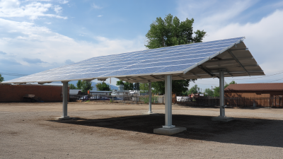
Carport or Canopy Structure Parking areas, commercial sites, campuses, and locations requiring shade or weather protection. Verify foundation locations, vehicle clearances, drainage, column protection, accessible routes, lighting integration, and construction sequencing around occupied parking. Check structural loads, impact protection, fire access, electrical equipment clearances, water drainage, corrosion protection, and local accessibility requirements. Large elevated surfaces can attract substantial wind loads. Design must consider site exposure, snow drift, drainage, seismic actions, and accidental vehicle impact where applicable. Inspect columns, foundations, roof drainage, sealants, fasteners, corrosion, lighting, cable trays, and vehicle-impact protection. Combines solar generation with parking shade and may avoid using additional undeveloped land. Usually requires higher steel quantities, deeper foundations, traffic control, and more complex construction coordination.
Selection rule: Choose the structure only after confirming the site survey, roof or soil condition, local wind and snow loads, drainage, fire access, electrical grounding, structural calculations, and permit requirements. Wind, snow, seismic, and foundation values must be calculated for the specific project rather than copied from a generic table.
Standards commonly used for verification: Applicable editions of IEC 62548 for photovoltaic array design, IEC 60364-7-712 for low-voltage PV installations, IEC 62446-1 for system documentation and verification, local building and electrical codes, and regionally applicable structural standards such as ASCE 7, Eurocodes, or national equivalents. The governing authority and project engineer should confirm which standards apply.